How do you place a needle accurately within hundredths of a milimeter inside an eye?
You’ll need hundreds of man hours, multiple Phd level engineers, an extremely precise robotic arm, a 200K$ microscope OCT imaging system and more.
Thankfully, I was able to join Prof. Iordachita and his team, who provided me all of the things above, to tackle this problem. How to place a needle inside a patients retina with micrometer accuracy using robotics and OCT imaging for subretinal injections?
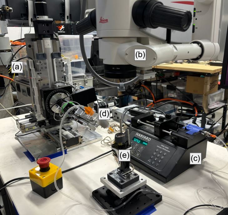
Subretinal injection is a procedure to inject therapeutic agents underneath the patients retina, which is the approximately 250 micron (quater of a milimeter) thick tissue found in the back of our eyes. They help us see by converting light into electrical signals that our brains can understand. It is usually done free hand by doctors with incredible dexterity and precision. Due to the precise nature of the task, robotic approaches are being researched by different groups all around the world. In this work I used the Steady Hand Eye Robot (SHER) built by the team at Johns Hopkins University.
There are two important layers for subretinal injections, the ILM and RPE. The ILM is the outermost layer of the retina and the RPE is the bottom most layer. The injection has to happen somewhere in between these two layers, ideally closer to the RPE without actually damaging them. RPE damage is irreversible and could potentially lead to vision loss.
Finally, the only modality that has high enough resolution to visualize this procedure is Optical Coherence Tomography (OCT). It is a light based imaging technique often used in eye operations.
Our initial idea was to train a segmentation network to detect the needle tip in OCT images and move this needle tip, with the help of the robot, to a target point selected by a doctor. But due to the deformations that happen when the needle pushes against the tissue, the initially selected target ended up moving to another spot and the needle would not be able to puncture the ILM layer ending up outside the retina.
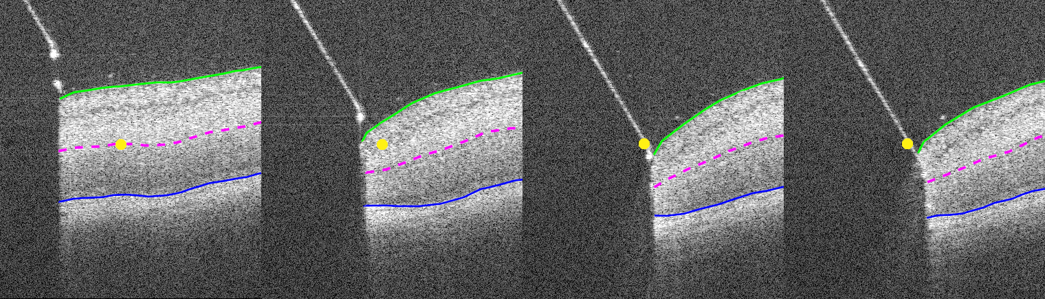
So we decided define the target with a relative depth between the ILM and RPE layers instead of a fixed point in space. This simplifies the target point into target layer but allows the target to move with the deformations. Since the injected drugs already cover a lot of space, the exact injection location can be moved a little without issues. We decided to call this layer the virtual target layer.
The second problem was to keep the needle inside of the OCT image at all times. Since the OCT image only gives you the scan of a 2D plane, the needle often moved to the right or left disappearing from the image. Thankfully, our OCT microscope system allows us to scan multiple 2D images right next to each other and combine them into a volume. In order to still have real time image data we could not take too many images. So we decided on 5 images that would be combined to create what we call B5-scan. In our microscope we could acquire a B5-scan at 9 Hz allowing for real time imaging.
Finally, putting everything together, our system takes B5-scans of the needle insertion, the resulting OCT volume is segmented using U-Net segmentation model that was trained on a custom dataset labelled by me. The segmentation results are then converted into a 3D point cloud and further processed to calculate the position of the virtual target layer. We can then select the tip points of the needle in the point cloud and move the needle along its needle axis until the virtual target layer is reached.
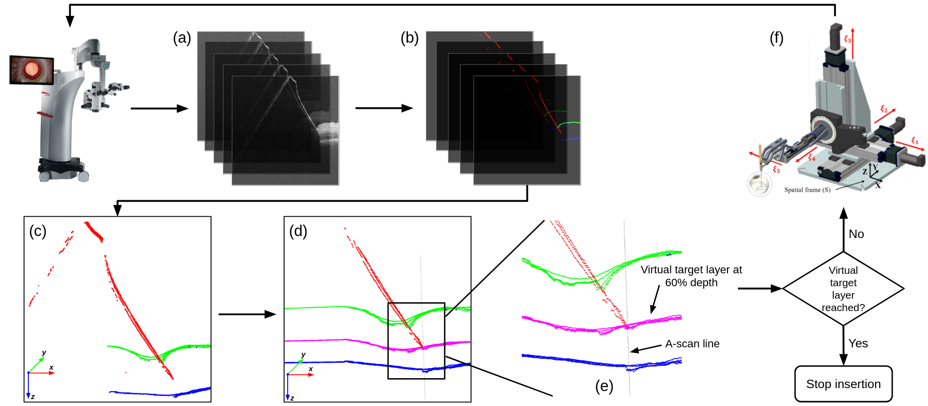
We tested our method on pig eyes and achieved an accuracy of 25 micrometers in reaching the virtual target position. This result is acceptable based on the size of the targets selected by doctors.